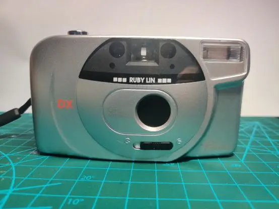
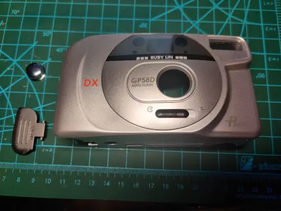
This is a film camera teardown article. Today we’re disassembling a film camera. This camera was designed and manufactured by the Japanese company Instax in 1998, and the disassembly reveals its extremely intricate internal structure.
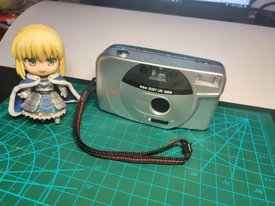
■ PART 1 Appearance
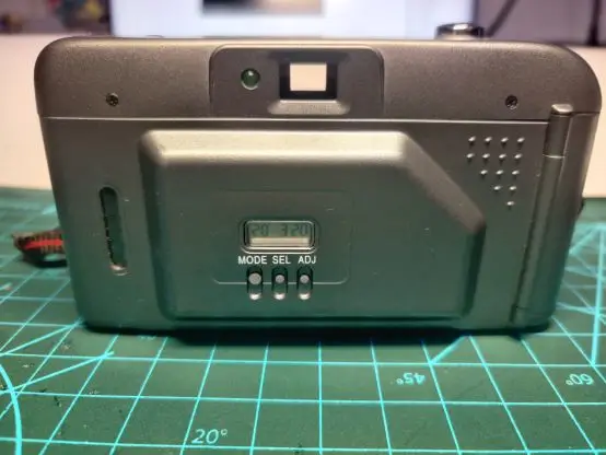
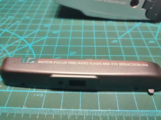
■ PART 2 External Disassembly
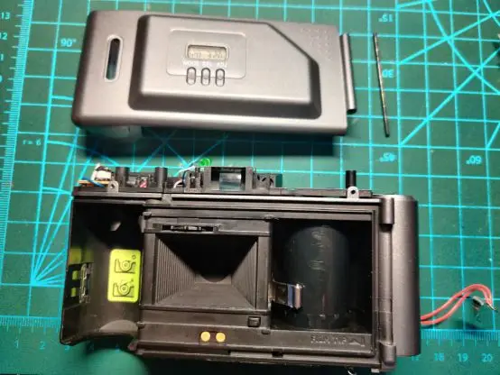
First, open the rear cover latch on the left side of the device. After removing the screws, you can gently pry up the top cover.
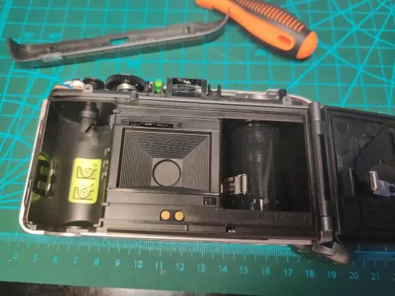
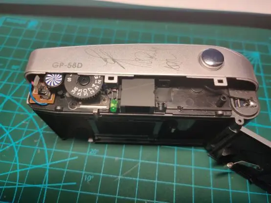
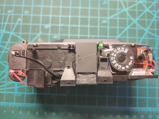
After removing the top cover, you can see physical display dials on the left side showing the film roll rotation and the remaining film quantity. It is presumably connected by gears, and the film display dial completes exactly one revolution after the entire roll of film has finished spinning. The image in the middle is a lens viewfinder.
Remove all the screws on the outside; with a little force, you can remove the outer casing from the front.
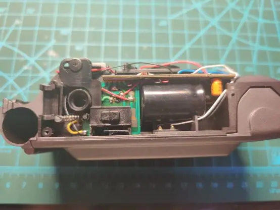
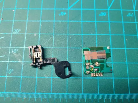
After removing the front cover, you can see the shutter button shaft on the left side, and its right side is connected to the circuit board located under the lens to control the shutter.
There is a physical switch below the shutter axis that can lock the shutter when the lens cap is closed, preventing it from being pressed.
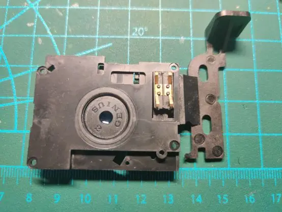
■ PART 3 Lens
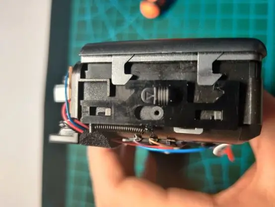
When the shutter is pressed, the connecting rod on the right side will press down and pull the aperture open, while simultaneously preparing the film spool to rotate.

Shutter and lens assembly 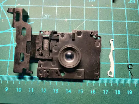
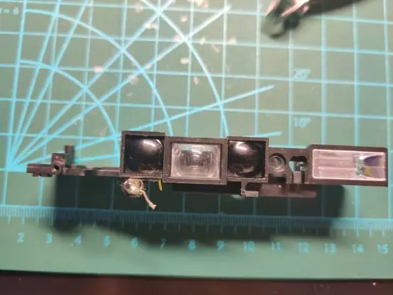
■ PART 4 Viewfinder | Flash
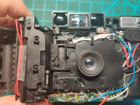
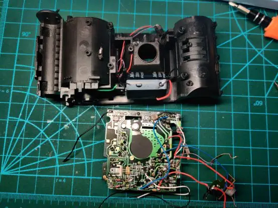
After removing the other visible screws on the front, the axis and lens can be removed, revealing the circuit board underneath. Two wires on the left side of the circuit board connect to the battery compartment. Above, the flash, indicator lights, film remaining display, and other components are connected.
Film Camera PCB backside
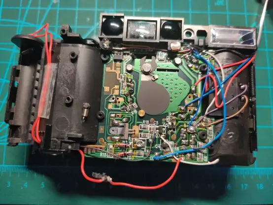
Film Camera Viewfinder and flash
Film Camera Backside Shell
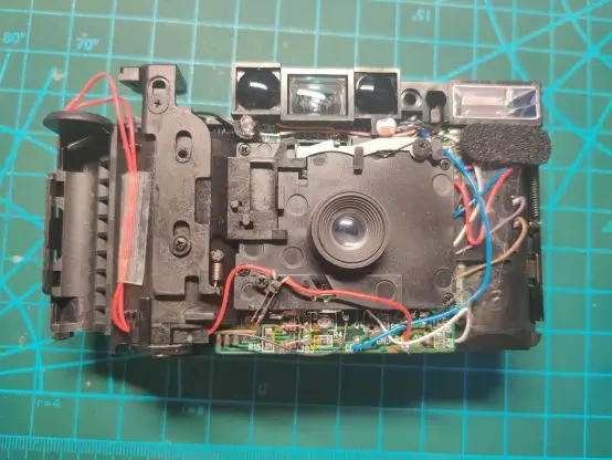
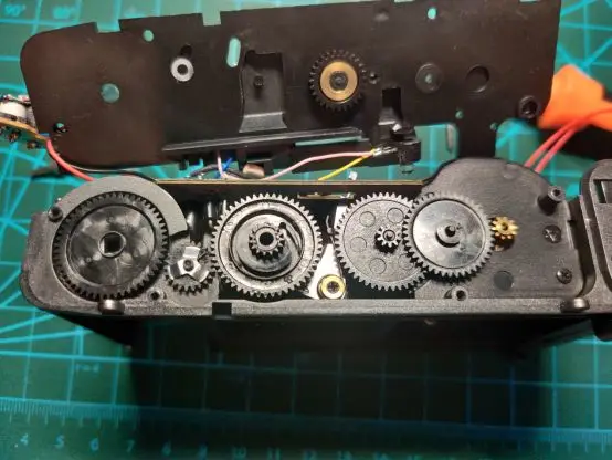
■ PART 5 Film Roll Transmission Gears
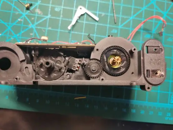
Below the camera is a large set of gears used to move the film and record data. Remove the gears, then remove the screw on the right side to reveal the motor located beneath them; this is the power source that drives the film.
■ PART 6 Film Camera PCB
Several electrodes are connected to the right side, located on the two film rolls and the closing sensor of the back cover. This design can detect and prevent errors caused by operational mistakes during shooting.
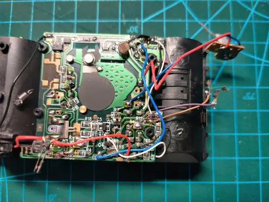
Below is another small circuit board, used to connect the large circuit board to the flash capacitor and motor.
After removing the large circuit board, we can see the main plastic frame inside the camera.
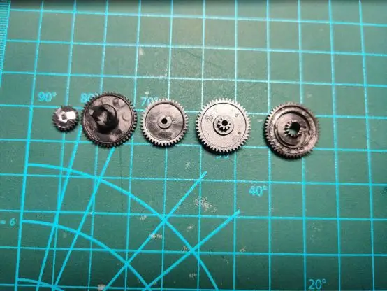
Once disassembled and arranged, the whole family should be neatly organized.
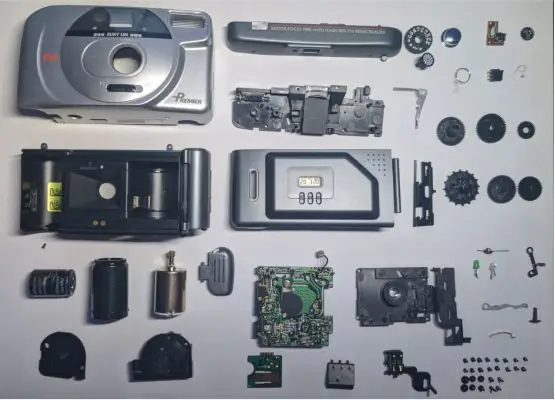
Through this teardown of a film camera, we can clearly see the delicate balance between mechanical structure, optical design, and material selection. Every detail plays a critical role in image quality, durability, and the overall shooting experience.
If you are looking for custom film camera development, structural optimization, or heritage camera recreation, feel free to contact us. With hands-on experience in film camera teardown, engineering design, and manufacturing, we are well equipped to deliver reliable, professional custom solutions — from concept to finished product.